Source: AVEC'92, 1992, pp.413-418
Integrated Chassis Control System for Improved Vehicle Dynamics
Shinsuke Sato, Hideo Inoue, Masaaki Tabata, and Shoji Inagaki
Toyota Motor Corp.
To improve stability, controllability and ride comfort, TOYOTA has developed as integrated chassis control system consisting of Active Four Wheel Steering (A-4WS), Active Hydropneumatic Suspension (A-SUS), ABS and TRC. The system, which is available on the current '91 model SOARER sold on the domestic market, realises a significant advance in total vehicle dynamics - due partly to the superior characteristics of the new A-4WS and A-SUS and partly to the enhancement accruing from integration - and makes an important contribution to active safety.
Key words: Chassis. Vehicle Dynamics. Integrated Control, Four Wheel Steering. Active Suspension
In order to improve vehicle behaviour and safety, many advances have bees made over the years to mechanical, electrical, hydraulic and pneumatic chassis components. During the last decade great progress in vehicle dynamics has been realised by various electronic control technologies. For example, anti-lock brakes (ABS) are available on most production models, while traction control (TRC), four wheel steering (4WS) (1) and controlled suspension (2) are becoming increasingly common. As a result of intense research, these control technologies now incorporate feedback terms to minimise the effects of external disturbances. To further enhance stability and controllability and raise the levels of safety, TOYOTA has recently bees working to achieve integration of the chassis control system. These efforts led to the integration of Active Four Wheel Steering (A-4WS), Active Hydropneumatic Suspension (A-SUS), TRC and ABS in the '91 model SOARER, which realises a drastic improvement in dynamic performance. This paper describes the concept of integrated control, examines the features of the newly developed integration system and shows how it succeeds is promoting active safety.
Broadly speaking, the controls affecting the dynamics of a two wheel drive vehicle fall into three categories
(1) Steering angle control (4WS)
(2) Driving/braking force control (TRC, ABS)
(3) Vertical load control (A-SUS)
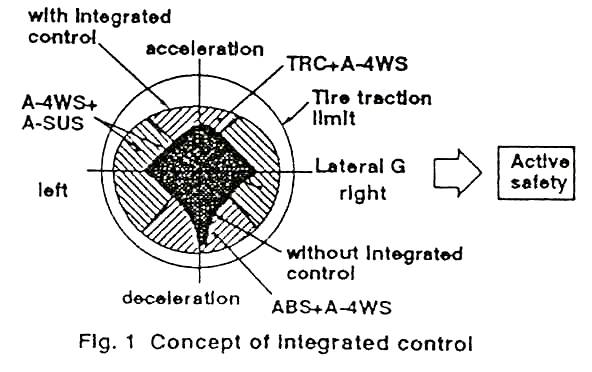
Fig. 1 illustrates the way in which integration of these controls can improve vehicle performance. The outer circle indicates the limit of tyre traction when vehicle dynamics are not considered; the shaded area shows the behavioural limits of a conventional vehicle; and the inner circle denotes the extended limits made possible by integration As can be seen, the interaction of A-SUS with A-4wS enables the steering angle to be increased even when lateral acceleration (G) is high, while the combination of A-4WS with TRC or ABS permits a far wider steering range during fast acceleration or deceleration. Consequently not only is active safety enhanced but driver stress is reduced as well.
| V | vehicle speed |
| q | steering angle |
| g | yaw velocity |
| Gy | lateral acceleration |
| Gyo | initial value of lateral acceleration |
| d f | front-wheel steering angle |
| d r | rear-wheel steering angle |
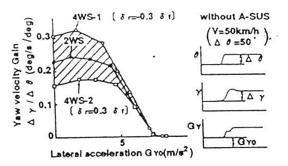
| Fig 2. Effect of steering angle control | |
When contemplating an integration system, careful attention must be paid to the domain of the individual controls. For example, Fig. 2 shows the effect of steering control on vehicle response. As can be sees, steering control is very effective whey lateral G is sufficiently low for there to be a linear relationship between the longitudinal and lateral forces acting anon the tires (linear range of cornering force But, as later G increases wad the tires enter the non-linear range of cornering force, the effect of steering control diminishes sharply. On the other hand, as Fig. 3 shows, roll stiffness distribution control greatly enhances controllability in this region. Thus the integration system must function so as to increasingly apportion priority to the control having the greatest effect.
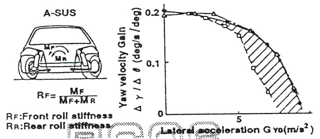
| dotted line: | Roll stiffness distribution control (with A-4WS) |
| line with squares: | Rf = 0.75 (with A-4WS) |
| line with triangles: | Rf = 0.5 (with A-4WS) |
| Fig. 3 Effect of roll stiffness distribution control | |
In accordance with the conceptual basis outlined above, as integration system for chassis controls has been developed. To ensure optimum performance, an entirely new active four wheel steering system and active hydropneumatic suspension system were designed and integrated with extant ABS and TRC systems.
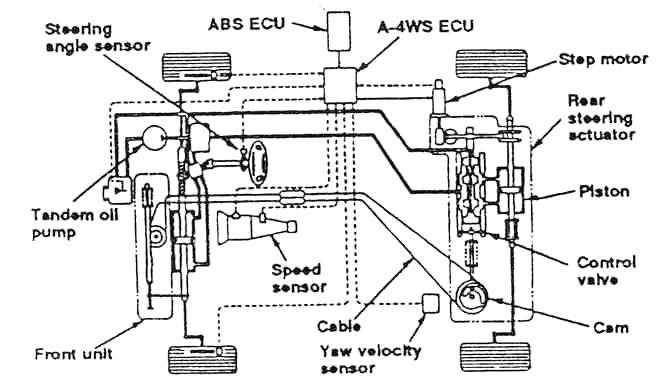
Fig. 4 Configuration of A-4WS system
The objectives set out for the new 4WS were:
Fig. 4 outlines the system that was developed to meet these requirements. Particular features of the system are the use of a yaw velocity sensor and of dual controls for the rear-steering actuator.
The yaw velocity sensor (Fig. 5) is a tuning fork vibration type autogyro, which measures the turning angular velocity of the vehicle by detecting the Corioli's force generated in a transducer.
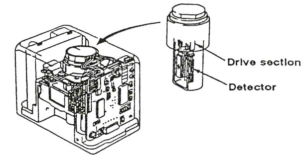
Fig. 5 Yaw velocity sensor
Figure 6 presents the advanced 4WS strategy that was devised to incorporate proportional steering angle and yaw velocity feedback so as to improve not only the steeling response but also stability against external disturbance. The rear steering actuator is hydraulically controlled by an electric step motor to provide steering angle of up to +/- 1.0 degree for active control at speed and by a cable and cam to provide up to +/- 5.0 degree of steer for greater manoeuvrability at low speeds.
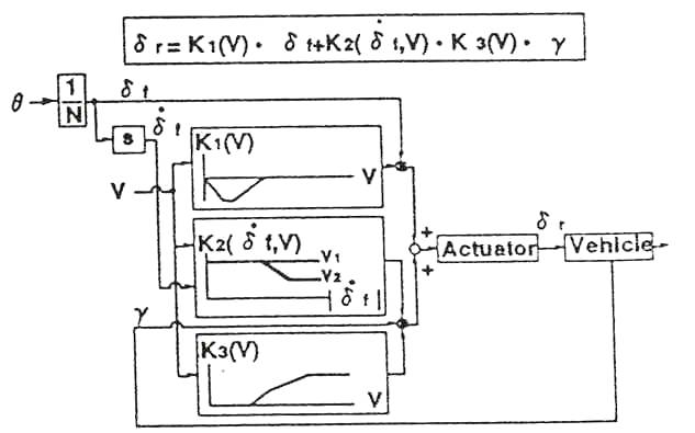
| d f | front-wheel steering angle |
| d ? | front-wheel steering angle velocity |
| d r | rear-wheel steering angle |
| V | vehicle speed |
| g | yaw velocity |
| K1 | steering angle proportional coefficient |
| K2 | tuning coefficient of yaw velocity proportional term |
| K3 | yaw velocity proportional coefficient |
| N | steering gear ratio |
| Fig. 6 Block diagram of A-4WS control | |
To confirm the efficacy of the A-4WS, test vehicles were subjected to a crosswind without corrective steering being made by the driver. As Fig. 7 shows, the lateral displacement with A-4WS was much less than with 2WS, which under these conditions would be the equivalent of conventional 4WS.
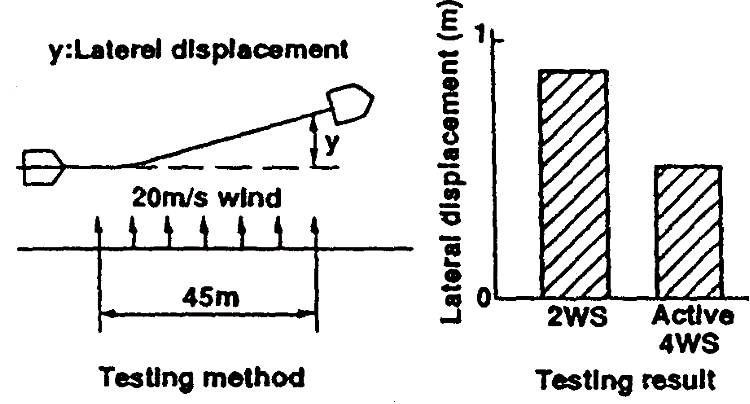
Fig. 7 Stability against crosswind
The A-SUS objectives were:
(1) improved ride comfort
(2) greater stability and controllability
(3) reduced roll, pitch and bounce
Fig. 8 shows the system developed to satisfy these objectives. A block diagram is shown in Fig. 9.
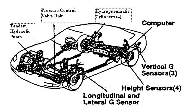
Fig. 8 Configuration of A-SUS system
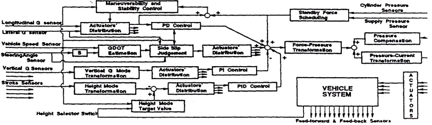
Fig. 9 Block diagram of A-SUS control
Features of the system are:
(1) Hydropneumatic cylinders replace the conventional springs in order to effectively utilise vertical load control.
(2) Vertical acceleration sensors are used for sky hook damping control.
(3) A variable displacement piston pump (Fig. 10) regulates the oil flow so that energy consumption is reduced when high loads are not required.
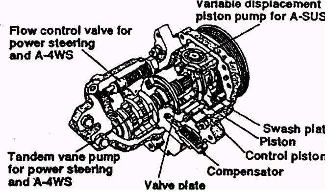
Fig. 10 Variable displacement piston pump
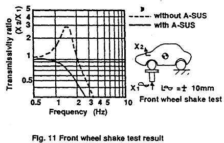
Fig. 11-14 indicate some of the advantages of the A-SUS system. Ride comfort is superior as pitching and bouncing are virtually eliminated (Fig. 11).
Because vehicle attitude is controlled, roll angle is drastically reduced throughout the whole lateral G range (Fig. 12) and maximum lateral G during cornering is increased (Fig. 13).
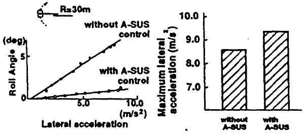
Fig. 12 Comparison of Roll Angle Fig. 13 Comparison of maximum lateral G
Roll stiffness distribution control greatly reduces the effort required of the driver when a curve suddenly becomes tighter, as can be seen from the lissajous traces in Fig. 14.
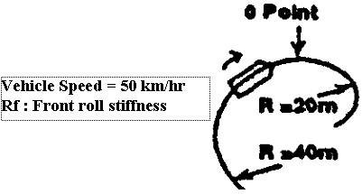
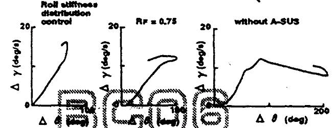
Fig. 14 Effect of roll stiffness distribution control
These results clearly demonstrate that by maintaining the vehicle in a flat attitude, not only is the comfort level raised but stability and cornering performance are improved since camber and toe-in are maintained at the correct angle, while controllability is enhanced as a result of the roll stiffness distribution control.
Fig. 15 shows how the. various controls are integrated. In order to achieve optimum overall dynamic performance and boost the effectiveness of each individual system, the concept of interactive adaptive control is applied. As shown in Fig 16. the calculated target value for a given performance A is calculated on the basis of all relevant performances and the gain is likewise modified not only according to feedback A but also according to the other performances.
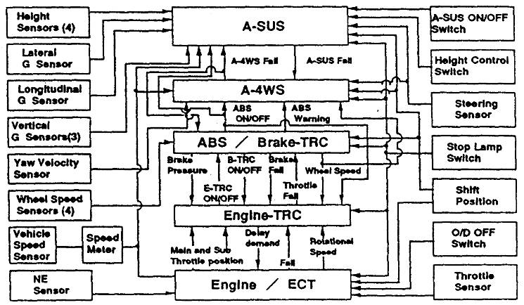
Fig. 15 Block diagram of integrated chassis control system
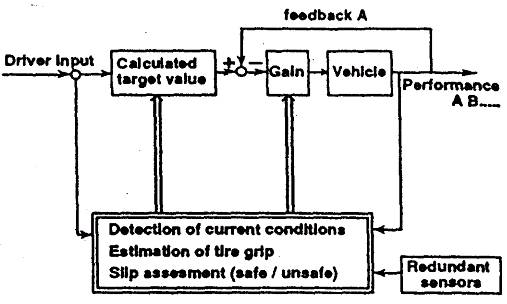
Fig. 16 Interactive adaptive control
For example, vehicle stability during braking can be assured by the interaction of A-4WS and ABS. Normally, for better manoeuvrability, the yaw velocity feedback coefficient is decreased as vehicle speed is reduced. But, while the ABS is operating, the yaw velocity feedback coefficient should be high. Hence the integrated control functions to fix the coefficient at the value pertaining at the moment the ABS commences operation (Fig. 17). As a result, stability is improved both in emergency braking and in braking on a slippery surface. Furthermore, because the ABS system need not be concerned with vehicle stability, which is assured by the A-4WS, its prime function can be assigned to realising the shortest braking distance.
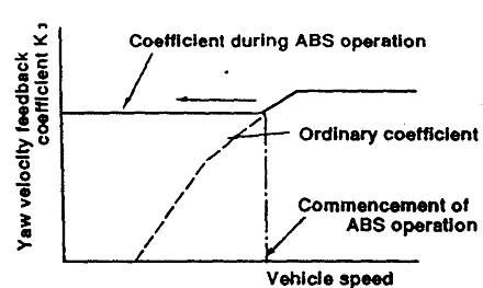
Fig. 17 Yaw velocity feedback coefficient during ABS operation
Fig. 18 gives another example of the way in which integration can boost the performance of an individual control, in this case A-4WS. In order to obtain the maximum benefit of A-4WS at high speeds, the yaw velocity feedback coefficient must reach its optimum value. But, with conventional suspension, a high value tends to cause a transient roll, identifiable as a peak in roll angle gain, before this optimum value can be attained. However A-SUS, eliminates this peak and thus eliminates the limit imposed on the yaw velocity feedback coefficient. Consequently the peak in yaw velocity gain is diminished and extended to a far higher frequency of steering angle.
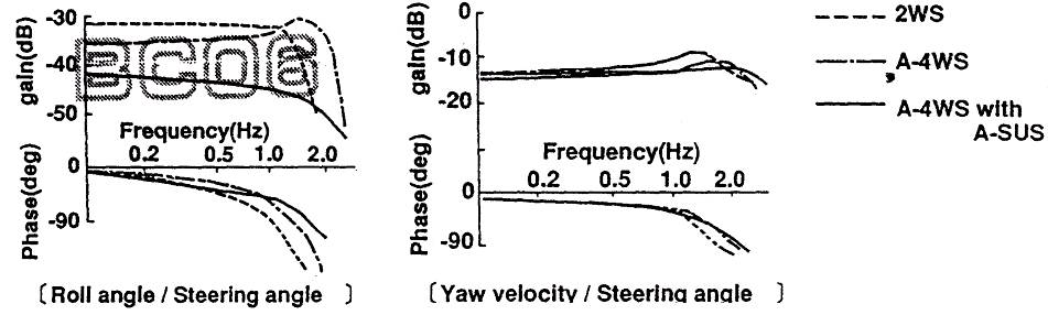
Fig. 18 Improvement in A-4WS due to integration with A-SUS (Frequency response in steering input)
Naturally reliability and fail-sate precautions are vital considerations for any control system. Here too, integration plays an important role in raising standards. For instance, yaw velocity is a key signal in the A-4WS system. For redundancy, measured yaw velocity is continuously compared to two reference values calculated from the sensor signals of other systems (Fig. 19). Should the measured yaw velocity be judged to have failed, backup control is instigated. This ensures that the vehicle's steering performance is always superior to that of the 2WS version.
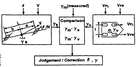
| t | tread |
| Vfl, Vfr | measured wheel speed |
| gm | measured yaw velocity |
| gv | yaw velocity calculated from Vfl, Vfr and tread |
| gs | yaw velocity calculated from q and v |
Fig.19 Redundant design of yaw velocity |
|
Various tests were conducted to evaluate the efficacy of the integrated chassis control system. Fig. 20 compares the results for emergency obstacle avoidance. In this situation fast, accurate response and quick convergence of yaw and lateral acceleration are essential. Controllability in the non-linear range of cornering force is also momentarily required. Hence the integrated control greatly increases the initial speed at which the manoeuvre can be safely carried out. From the lissajous figures of driver steering input and generated yaw velocity, it can be seen that even at the greater speed, the interaction of A-4WS and A-SUS makes the vehicle far easier to control.
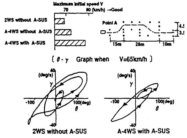
Fig. 20 Test results I : emergency obstacle avoidance
Fig. 21 shows vehicle performance when changing from a slower to a faster moving lane on a slippery surface. In a conventional vehicle, very delicate control of the steering wheel and accelerator pedal is required during this manoeuvre to prevent the vehicle from spinning. As the results confirm, traction control by itself significantly improves vehicle stability, but when TRC is integrated with A-4WS and A-SUS an even more drastic improvement is realised. This indicates that integrated control renders the vehicle intrinsically safer.
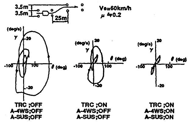
Fig. 21 Test results II : lane-change while accelerating on a slippery surface
Fig. 22 shows braking performance on a split µ surface (i.e. a surface having different coefficients of friction for the off-side and near-side wheels). Again, the driver of a conventional vehicle must exercise considerable skill in these circumstances. ABS considerably eases the steering input necessary to maintain stability but nevertheless safety margins are still fairly slim. However, ABS in concert with A-4WS enables the vehicle to be braked to a halt with only minimum steering correction necessary to maintain a straight course.
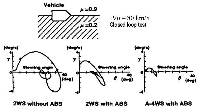
Fig. 22 Test results III: braking on split µ surface
However, the authors firmly believe that in view point of the vast potential for
increasing active safety offered by integration, continual efforts must be made to
decrease costs and power consumption and increase sophistication so that more and more
efficacious systems can be realised.
(1) M.Yamamoto, et al., "Improvement of Steering and disturbance response by Active controlled rear wheel steer (study on Active control for vehicle dynamics: 1st Report)", proceedings of the JSAE annual conference 892, 1989, 892128
(2) T.Yonekawa, et al., "Effect of Active control suspension system on vehicle dynamics", JSAE spring convention proceedings 90., May 1990, 901039.
(3) Y.Matsuo, et al.,"Development of experimental vehicle with integrated chassis control (Study on Active control for vehicle dynamics:2nd report)", proceedings of the JSAE Annual conference 892. Oct. 1989, 892129
(4) H.Tanaka, et al.," Development of Vehicle Integrated Control System". FISITA 92, June 1992
(5) H.Inoue, et al. "Development of an integrated Chassis Control System for improving Vehicle Dynamics", Journal of JSAE. No.3, 1992 (6) 1.G.Riverd,"Automobile Electronics in the year 2000". SAE 861027, Oct. 1986
