|
UZZ32 Active Computer Diagnostics |
|
UZZ32 Active Computer Diagnostics |
Hi all Active owners,
just wanted to update all on my suspension saga.
But first, I just wanted to encourage everyone to share info on these cars. I've just spent 2 months trying to figure out my issue and gave a crap load of money to someone to try and fix it. Although I'm not mechanically minded, I'd sure like to give anyone a hand to save them going through what I have over the last couple of months.
With my problem, we installed an alarm and the active error came up. Ran diagnostics and SUS 11 came up. A guy from Japan told me it was left front sensor. Pulled that out, looked at all fuses, visual inspection of wiring, even swapped the height relay with Peter Scott's car, (which by the way is the main relay switch on the cooling fan apparently) and could not find anything.....
Then, I gave it to an electrician (OG Electrical) -The active suspension computer has a number output and input pins. Each of these pins should register a specific voltage range both for output and input signals. Where there is a variance, the manual will tell you where to look. In my case, there was no signal coming back from the left front height sensor or lateral G sensor. The electrician then traced the wiring from the computer to the height sensor and under the passenger kick panel discovered a plug had been disconnected (this is where the alarm installer jacked into the fuel pump loom and must have knocked the plug.)
Now my active does the 'active dance' and handles like it should.
It cost me 500 bucks to learn the above but now I have some info on what the input/output pins should be reading and I'm more than happy to share. I'll have to scan the papers but I'm happy to post them to anyone having problems.
The tables below are also available in easy to print Adobe Acrobat file (pdf). activecomputer.pdf (90kb)
UZZ32 - HYDROPNEUMATIC SUSPENSION COMPUTER
|
|||
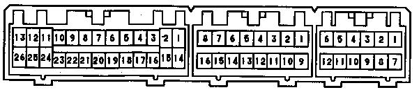
Connector A |
Connector B |
Connector C |
|
|
|||
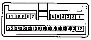
Connector D |
|||
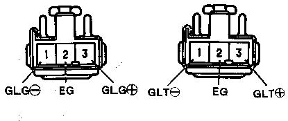
Lateral G Check Connectors, before and after |
|||
|
|||
Connector A (White) |
Connector B (Grey) |
||
| Connector | Pin No | Pin Code | Input/Output | Item Measured | Tester contacts + ó - |
Measurement Conditions | Standard Value | Location of Problem if value not in standard range |
| A | 1 | TC | In | Voltage | A1ó C7 | Ignition ON, and diagnosis connector or TDCL pins Tc-E1 shorted | 1V or less | Diagnosis Connector |
| Ignition ON, and diagnosis connector or TDCL pins Tc-E1 open | 8 – 14V | TDCL | ||||||
| 2 | ES -1 | In | Continuity | A2ó C7 | Ordinary Conditions | Continuity | G Sensor shielding wire before and after | |
| 3 | TOIL | In | Voltage | A3ó C7 | Idling | 0.5 – 4.5V | Oil temperature sensor | |
| 4 | PRL | In | Voltage | A25 A3ó Or A26 |
Idling | 0.6 – 4.5V | Rear (LH) pressure sensor | |
| 5 | GLG | In | Voltage | A5ó A24 | Ignition ON | 0.5 – 4.5V | Horizontal? G Sensor, before and after | |
| 6 | HFL | In | Voltage | A25 A6ó or A26 |
Ignition ON | 0.5 – 4.5V | Front (LH) height control sensor | |
| 7 | HRL | In | Voltage | A25 A7ó or A26 |
Ignition ON | 0.5 – 4.5V | Rear (LH) height control sensor |
| Connector | Pin No | Pin Code | Input/Output | Item Measured | Tester contacts + ó - |
Measurement Conditions | Standard Value | Location of Problem if value not in standard range |
| A | 8 | SGFL | In | Voltage | A25 A8ó or A26 |
Ignition ON | 0.5 – 4.5V | Front (LH) upper and lower G sensor |
| 9 | SGRL | In | Voltage | A25 A9 ó or A26 |
Ignition ON | 0.5 – 4.5V | Rear (LH) upper and lower G sensor | |
| 10 | PACC | In | Voltage | A25 A10 ó or A26 |
Idling | 0.5 – 4.5V | Accumulator pressure sensor | |
| 11 | VG5 | Out | Voltage | A11 ó A24 | Idling | 4.7 – 5.3V | Computer | |
| 12 | VL5 | Out | Voltage | A25 A12 ó or A26 |
Idling | 4.7 – 5.3V | Computer | |
| 13 | VR5 | Out | Voltage | A25 A13 ó or A26 |
Idling | 4.7 – 5.3V | Computer | |
| 14 | TS | In | Voltage | A14 ó C7 | Ignition ON, and diagnosis connector or TDCL pins Ts – E1 shorted | 1V or less | Diagnosis connector | |
| Ignition ON, and diagnosis connector or TDCL pins Ts – E1 Open | 8 – 14V | TDCL connector |
| Connector | Pin No | Pin Code | Input/Output | Item Measured | Tester contacts + ó - |
Measurement Conditions | Standard Value | Location of Problem if value not in standard range |
| A | 15 | ES2 | In | Continuity | A15 ó C7 | Ordinary Conditions | Continuity | Lateral (Transverse?) G sensor shielding wire |
| 16 | TD | In | Voltage | A16 ó C7 | Ignition ON, and TDCL
pins Td - E1 shorted |
1v or less | TDCL Connector | |
| Ignition ON, and TDCL pins Td – E1 open | 8 – 14v | |||||||
| 17 | PRR | In | Voltage | A17 ó A26 | Idling | 0.5 – 4.5v | Rear (RH) Pressure Sensor | |
| 18 | GLT | In | Voltage | A18 ó A24 | Ignition ON | 0.5 – 4.5v | Lateral G sensor, before and after | |
| 19 | HFR | In | Voltage | A25 A19 ó or A26 |
Ignition ON | 0.5 – 4.5v | Front (RH) height control sensor | |
| 20 | HRR | In | Voltage | A25 A20 ó or A26 |
Ignition ON | 0.5 – 4.5v | Rear (RH) height control sensor | |
| 22 | SGRR | In | Voltage | A25 A22 ó or A26 |
Ignition ON | 0.5 – 4.5v | Rear (RH) upper and lower G sensor |
| Connector | Pin No | Pin Code | Input/Output | Item Measured | Tester contacts + ó - |
Measurement Conditions | Standard Value | Location of Problem if value not in standard range |
| A | 24 | EG | In | Continuity | A24 ó C7 | Ordinary Conditions | Continuity | Computer |
| 25 | EL | A25 ó C7 | ||||||
| 26 | ER | A26 ó C7 | ||||||
| B | 1 | SS1 | In | Voltage | B1 ó C7 | Ignition ON, and turning steering wheel slowly | Changes between 1v or less and 5v or more | Steering Sensor |
| 5 | 4WSF | In | Voltage | B5 ó C7 | Ignition ON | 8 – 14v | 4WS computer | |
| 6 | Voltage | B6 ó C7 | Ignition ON | 8 – 14v | ABS computer | |||
| 7 | Voltage | B7 ó C7 | Ignition ON | 8 – 14v | Oil level sensor | |||
| 8 | Voltage | B8 ó C7 | Ignition ON, and suspension control switch at NORM position | 8 – 14v | Suspension control switch | |||
| 9 | Voltage | B9 ó C7 | Ignition ON and turning steering wheel slowly | Changes between 1v or less and 5v or more | Steering Sensor | |||
| 10 | Voltage | B10 ó C7 | Ignition ON, and travelling slowly | Changes between 1v or less and 5v or more | Speed Sensor | |||
| Connector | Pin No | Pin Code | Input/Output | Item Measured | Tester contacts + ó - |
Measurement Conditions | Standard Value | Location of Problem if value not in standard range |
| B | 12 | STP | In | Voltage | B12 ó C7 | Ignition ON, and brake switch ON | 10 – 14v | Stop light switch |
| 14 | AFFSW | In | Voltage | B14 ó C7 | Ignition ON, and suspension control switch ON | 10 – 14v | Suspension Control Switch | |
| 16 | ICL | In | Voltage | B16 ó C7 | Idling | 8v or more | IC regulator | |
| C | 1 | +B | In | Voltage | C1 ó C7 | Ignition ON | 10 – 14v | HPS fuse |
| 2 | GLG + | In | Voltage | C2 ó C7 | Ignition ON, and Connector b GLG + to EG pin is OPEN | 5v or more | Lateral G sensor before and after | |
| Ignition ON, and Connector b GLG + to EG pin is SHORTED | 1v or less | |||||||
| 3 | GLT + | In | Voltage | C3 ó C7 | Ignition ON, and Connector a GLT+ to EG pin is open | 5v or more | Lateral G sensor before and after | |
| Ignition ON, and Connector a GLT+ to EG pin is shorted | 1v or less | |||||||
| Connector | Pin No | Pin Code | Input/Output | Item Measured | Tester contacts + ó - |
Measurement Conditions | Standard Value | Location of Problem if value not in standard range |
| C | 4 | ES4 | In | Continuity | C4ó C7 | Ordinary Conditions | Continuity | Computer |
| 5 | ES3 | C5 ó C7 | ||||||
| 7 | GND | Out | Continuity | C7 ó Body earth | Ordinary Conditions | Continuity | Computer Body Earth |
|
| 8 | GLG | In | Voltage | C8 ó C7 | Ignition ON, and Connector a GLG – to EG pin open | 5v or more | Lateral G sensor before and after | |
| Ignition ON, and Connector a GLG – to EG pin shorted | 1v or less | |||||||
| 9 | GLG | In | Voltage | C9 ó C7 | Ignition ON, and Connector a GLT – to EG pin open | 5v or more | Lateral G sensor before and after | |
| Ignition ON, and Connector a GLT – to EG pin shorted | 1v or less | |||||||
| 10 | ES5 | In | Continuity | C10 ó C7 | Ordinary conditions | Continuity | Computer | |
| 12 | PN | In | Voltage | C21 ó C7 | Ignition ON, and shift lever in P or N range | 10 – 14v | Neutral start switch |
Connector |
Pin No | Pin Code | Input/Output | Item Measured | Tester contacts + ó - |
Measurement Conditions | Standard Value | Location of Problem if value not in standard range |
| D | 1 | +B | In | Voltage | D1 ó C7 | Ignition ON | 10 – 14v | HPS fuse |
| 2 | BAT | In | Voltage | D2 ó C7 | Ordinary Conditions | 8-14v | ECU-B fuse | |
| 3 | HPSF | Out | Voltage | D3 ó C7 | Ignition ON | 9 – 14v | Computer | |
| 4 | ACTV HIGH | Out | Voltage | D4 ó C7 | Idling, and suspension control switch on HIGH | 10 – 14v | Combination meter | |
| 5 | ACTV SUS | Out | Voltage | D5 ó C7 | Idling | 1v or less | Combination meter | |
| 6 | ACTV OFF | Out | Voltage | D6 ó C7 | Ignition ON, and suspension control switch OFF | 1v or less | Combination meter | |
| 7 | SFL+ | Out | Voltage | D7 ó C7 | In idling stage, put shift lever into position other than P or the N range and/to achieve controlled stage, put shift lever in P or N range | 0.36 – 7.7v | The various absorber control solenoid valves | |
| 8 | SFR+ | D8 ó C7 | ||||||
| 9 | SRL+ | D9 ó C7 | ||||||
| 10 | SRR+ | D10 ó C7 | ||||||
| 11 | SBYP+ | Out | Voltage | D11 ó C7 | In idling stage, put shift lever into position other than P or the N range and/to achieve controlled stage, put shift lever in P or N range | 0.36 – 7.7v | Suspension control solenoid valve | |
Connector |
Pin No | Pin Code | Input/Output | Item Measured | Tester contacts + ó - |
Measurement Conditions | Standard Value | Location of Problem if value not in standard range |
| D | 12 | GND | Out | Continuity | D12 ó Body Earth | Ordinary Conditions | Continuity |
|
| 13 | IG | In | Voltage | D13 ó C7 | Ignition ON | 10 – 14v | ECU-IG Fuse | |
| 18 | TEM | In | Voltage | D18 ó C7 | Ignition ON | 1v or less | Diagnosis connector | |
| 19 | CRY | Out | Voltage | D19 ó C7 | Ignition ON, and suspension fluid at 70C or more | 10 – 14v | - Oil
temperature sensor - Computer |
|
| Ignition ON, and suspension fluid at 60C or less | 1v or less | |||||||
| 20 | RLY | Out | Voltage | D20 ó C7 | Ignition ON | 10 – 14v | Computer | |
| 21 | SFL | Out | Voltage | D21 ó Body earth | Ordinary Conditions | 0 – 0.5v | -
Computer - Body earth |
|
| 22 | SFR | D22 ó Body earth | ||||||
| 23 | SRL | D23 ó Body earth | ||||||
| 24 | SRR | D24 ó Body earth | ||||||
| 25 | SBYP | D25 ó Body earth | ||||||