 |
Power steering pump seal replacement |
|
Power steering pump seal replacement |
by Mel Grebowski.
| The most common problem with alternators on the V8 Soarer ( Active suspension not applicable) is the power steering fluid leaking from the power steering pump on to the alternator which is located directly under. The fluid makes its way into the interior of the alternator and causes some sort of a short, blowing the alternator up. A quick and cheap way to rectify this problem is to fix the power steering pump at the first site of any leaking fluid. The most common problem with the pump, is the failure of the main shaft seal and/or main shaft bearing which is just as responsible for the leaking as the seal itself. This particular pump uses a single bearing which once worn out has a tendency to deflect the pumps main shaft caused by the tension of the main serpentine belt, this in turn puts the seal under increase workload on the tension side allowing for a small gap to open up between the main shaft and the seal on the non-tension side, pressure of the fluid usually finds its way out and on to the alternator. | 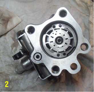 |
| Seal kits are available from Neil Griffiths and most Toyota dealers part # 04446-24012 , however these kits do not include the bearing, you will have to purchase the bearing separately from any good bearing store ( NTN 6303 ) you should not pay any more than AU $20.00 for one of those and as far as I know they are pretty common. Once you gather all your parts: seal kit, bearing and good power steering fluid you can start to pull your pump out. |
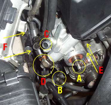 |
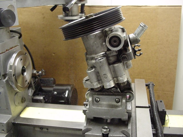
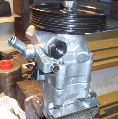
Photo on the left illustrates the pump assembly with the reservoir and
hoses removed. 1. Disconnect the radiator reservoir and move out of the way, 2. Drain and disconnect the power steering pump fluid reservoir, you may need a small container to drain into, remove from engine bay and wash with good engine degreaser. 3. Circle "C" and "B" indicate the reservoir hose connection, "C" is the inlet and "B" is the return. 4. With the main serpentine belt in place remove the main nut on the pump pulley, if the pulley slips, try tapping your spanner or socket wrench with a hammer repeatedly until it becomes loose in the anti clockwise direction. 5. Remove the main belt by tensioning the belt pre-tension pulley. 6. Remove the pump pulley. 7. Undo the bolt indicated "D" which is the Flow Control Valves outlet (Pressure Port Union) which connects to your steering rack. It is important to undo this union prior to undoing the main bolts "E" and "F" as it requires some force to undo it. 8. Undo the main bolts indicated at "E" and "F" there are two of each. 9. Your pump should be now ready for removal from the engine bay. |
 |
Wash the whole pump in good engine degreaser and wipe dry, take it to a dust free area and disassemble, remove the main body bolts ( it may be easier to hold the pump in the vice as illustrated to the left). |
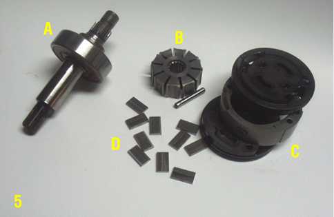
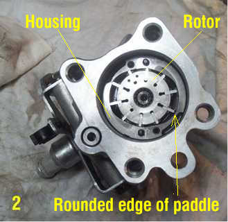
| Pull the pump apart, the main shaft will stay with the front
pump casing, inside the pump you should find the pump rotor housing, its made up of
several parts: A is the pump or main shaft with the bearing still attached, B
is the rotor itself with the guide pin or Straight pin next to it, C is made up of
two plates ( vane plates) and the rotor housing, D is the rotor paddles. Inspect all parts for wear in particular pay attention to the rotor housing and rotor paddles, should you discover deep scratches or gouges in the rotor housing you might consider either getting a reconditioned housing or having yours honed (number of engine recondition workshops provide a hone service for numerous parts ) the other part that may need attention could be the rotor paddles, small rectangular pieces of steel with one edge rounded and the other square, the square edge faces the centre of the rotor and the rounded edge faces the outside its also the edge that makes contact with the rotor housing. Once inserted in to the rotor, the paddles should sit nice and loose but without any side play, the centrifugal force of the rotating rotor pushes the paddles outward where they make contact with the rotor housing making a nice seal thus compressing the fluid. |
 |
| To remove the main shaft and bearing you will require a "C" clip or snap ring pliers, remove the snap ring located on the face of the bearing and discard as a new one will have to be used. Tap the shaft gently from the rotor side outwards and the bearing will slowly come out of the housing. Once the bearing and shaft are removed you will see the main shaft seal, push it out in the same direction as the bearing, you might need to use an aluminium of brass rod to punch it out. Replace the seal with a new one from the kit. First clean the seal housing with clean rag and lubricate with clean steering fluid, then position the seal with the "rubber" side facing outward and press it in to position or use a largest diameter socket that will fit in to the seal housing and using a hammer gently tap in to position as illustrated on the right ( "A" pictures the socket in position ) | 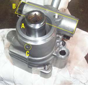 |
"B" indicates the " Flow Control
Valve" "C" indicates the little hole that is commonly used on water pumps and power steering pumps to indicate the failure of the seal with out affecting the bearing. Once you see fluid or water come out of this small hole your seal needs replacing. |
| To change the bearing on the main shaft you will need to remove the "Snap Ring" Use special pliers or if unavailable try using two medium flat screw drivers, once you pop the ring out of the groove in the shaft it should slide down and off the shaft with out too much trouble. push the old bearing off and discard, now inspect the shaft for any deterioration, pay particular attention to the area which comes in contact with the seal, the seal is rubber but you will be surprised the groves it can make in steel shafts! If any grooves or scratches are present they will need to be sanded out either on the lathe or in the drill, use a wet and dry sanding paper lubricated with WD40, start with coarse paper and work you way up (200 grit and up) try to get as many scratches out as possible without deforming the shaft. Now press the new bearing on to the shaft using a bearing press or by placing the bearing on the top of open jaws of a vice and gently tap the shaft through from the top until it finishes in its position. Use a hardwood packer between the shaft and hammer so no damage to the shaft occurs. If you discover any play between the new bearing and the shaft you may need to use some "Lock Tight" to "glue" the bearing to the shaft. Once the new bearing is in its position lock it in with a new "Snap Ring" from the kit, inset the bearing and shaft assembly in to the pump housing (lubricate the shaft and seal with clean power steering fluid) and insert a new "Snap ring " using "Snap ring" pliers. |
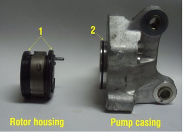 |
Next remove the old rubber "O" ring seals from the pump casing and rotor housing plates, you may need to use a pin to pull them out of the groove. In the seal kit you should receive 2 seals in one packet and 1 in another, the single seal goes on to the pump casing (indicated as number "2") and the two other go on to the rotor housing plates or vane plates as illustrated on the left (number "1"), lubricate the grooves and seals prior to installation to ease them in, make sure that they are not twisted and are sitting nice and straight in their grooves. |
 |
 |
 |
| Now its time to start reassembling the pump internals. Picture "1"
shows the front Vane or Rotor plate in position ( the difference between the front and the
rear plate is that the front one has the shaft going through the centre of it and the rear
one does not), lubricate the pump casing on the inside with new power steering fluid and
gently push the front plate all the way in making sure that the seal on the outside of the
plate has not moved, twisted or got pinched as it will damage the seal, so take your time
and lubricate plenty. When you are finished with the front plate it should look like
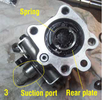
picture "1" Picture "2" illustrates the rotor housing, rotor and rotor paddles. The rotor has two small holes drilled in one of the faces which should be facing out as pictured, again, lubricate with new fluid and insert the paddles in the the rotor making sure that the rounded edges of the paddles are facing outward (VERY IMPORTANT) also make sure that the guide pin is inserted from the front plate through the rotor housing and the rear plate. Picture "3" illustrates the rear plate in position with the spring on top. Before you put the rear plate on it would be a good idea to put some more fluid in to the pump interior as it will run "Dry" for a while when its reinstalled in the engine bay. Again be very careful when inserting the rear plate in as the seal can twist etc so take your time and lubricate plenty. Now your pump is ready to have the front and back put back together, you will need to use the main body bolts to press the whole unit together as the spring will create a bit of pressure on the internals, lubricate the seal on the pump casing and by doing up the opposite bolts, you should be able to watch the seal slide gently and evenly in to the pump. Once the pump is together, you can change the suction port union's "O" ring seal which is located between the pump body and port itself. Undo the two small bolts holding the suction port, separate from pump, clean the area and lubricate. Once you have positioned the new "o" ring in place, gently press together and bolt. |
| Last stage should be the removal of the big black nut ( Pressure Port Union) from the "Flow Control Valve" in order to dismantle the valve itself. Once the nut is removed, the valve assembly should pop out as its spring loaded. The back of the valve assembly has a "plug" that's retained in place with a "Snap" ring and needs to be removed, using a bolt that will fit in to the threaded hole in the plug it can be pulled out, this bolt will be used again in reinstallation of the plug. ( from memory I think its M10 bolt ) There are two small "O" ring seals that sit in little groves at the front and at the back of the valve assembly as indicated on the picture as: "O" ring. Clean the valve assembly and replace seals as previously remembering to lubricate, put the assembly back in to the pump body and you are done. | 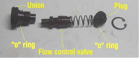 |
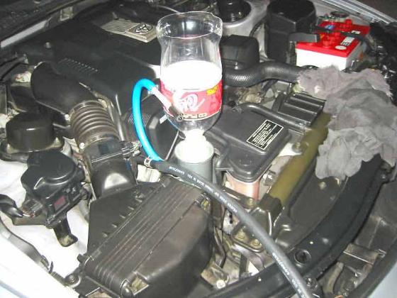
| The pump can now be installed on to the engine using the removal procedure in reverse. Fill the reservoir with fresh fluid, jack the front of the car of the ground ( if you have air suspension remember to switch the suspension switch in the boot to "OFF" position as damage to your suspension may occur, not quite sure if the guys with Active suspension need to do similar ?) start you engine and at idle rotate the steering wheel left to right full lock pausing for a second on full lock, (5 to 10 times) at first you will hear a "squishing" noise coming from your pump ( it's the air and fluid mixed together) hopefully it will get better each time you do a full "lock to lock" maneuver, you may need to have an assistant topping up your reservoir with fluid as you do this exercise, if you are on your own you may need to top it up yourself. It will also pay to stop the engine once you think you can't get it any better and re do the above half an hour later, once the bubbles of air had a chance to separate from the fluid. Check the fluid level, do not over fill the reservoir, regularly check for leaks from the seal area and hoses. I would also suggest that you replace the factory hose clamps ( the ones you have to use pliers to open up) with regular Stainless Steel hose clamps (the ones you use a screw driver to open and tighten) on your reservoir hoses as the factory clamps don't normally like to be reused, its hard to get them back in to the original position and you'll find that they have the tendency to leak. Special Thanks to Neil Griffiths from Rush Imports , please visit his site for any Soarer requirements. Also all the guys from ALSC forum. There is another excellent power steering pump tutorial on http://www.lexls.com/tutorials/steering/pspumprebuild.html
You can also flush your power steering as shown here: http://www.lexls.com/tutorials/steering/psflush.html and here Soarer Central Power Steering flush by Andrew Vlamos
|
| Disclaimer: Information provided on this page together with all the links is free of charge and intended for your information only, sale, reproduction or distribution for commercial purposes of text, pictures and drawings is forbidden by the Author/s. Author/s do not accept any responsibility for actions or damages caused by the above information. If you do not feel fully comfortable with your ability to perform any of the above tasks and/or do not fully understand the procedure, do not attempt the above project/s as damage to yourself, your vehicle, components your trying to install or third parties and their property, may result from your actions. Please check if modifications you are about to perform are legal in your state or country. Some modifications done to your vehicle may impact on your warranty and/or insurance so check with your car supplier and/or insurance company, tools used on this page may require skill and knowledge in order to reach the required end result in presented quality, if you do not poses the skills your end result may differ from the above. Power tools are dangerous, wear protective clothing and eye glasses. |
![]()