 |
Make your own BFI (big intake) |
|
Make your own BFI (big intake) |
by Peter Scott
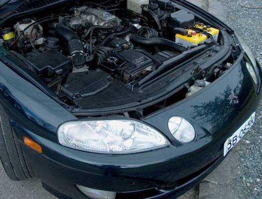
This is my 2nd BFI - hardly know it was there looking at the engine bay. Current one is now BFI3
An up to date list of the bits you will need and some templates to download are now available.
Check out BFI Hardware List and Reviews - essential if you want to make your own BFI
The elephant snorkel pictured above worked great but not good enough. I have decide to make the hole in the airbox bigger. 6 inch diameter (equivalent) is not big enough. The standard hole is a joke.
I am using the natural car surfaces as much as possible. Taking off from he lights you want to let the engine suck in as much cold air as it wants. The Ram Air effect is neglible.
I have virtually removed the entire front of the airbox now. Only a small rim remains for strength. You can see the whole filter (genuine of course) through the enourmous hole.
Next is some closed cell EVA foam - a great insulator (it's used for a sleep on mat for camping) - $10 buys more than you need. I have sealed the sides of the airbox from the engine bay with this foam. I found before that hot air from engine bay made acceleration times longer. A small strip of foam on top of airbox seals along there. So the front of the airbox is sealed using the bonnet and natural sides of the car as much as possible with a little foam rubber to help - all the air comes in form under the headlight (which is no longer restricted by having some sort of pipe under it). Did I mention the hole is huge?!
This is stage one.
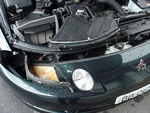
The headlight fits so much better with out trying to fit anything under it. Next is a sheet of plywood that fills the hole under the headlight. On top of this a strip of foam (it is black high density, water,air proof) that seals against the flat bottom of the headlight and curves to direct airflow around from the massive chamber behind the high beams. The leading edge of the curved plastic piece in front of the radiator is then moved down and used as the air scoop.
You can convert the standard airbox yourself to be a BFI real cheap - I will put some pics up soon - i don't have a digital (like my brother does) so I have to develop plain old film then scan them in.
Hot 4's had an article on Inlet Resonator Chambers - the V8 one is 1.2 litres ( I measured it). The chamber reduces noise and improves volumetric efficiency). Sure enough with the chamber the one I made was very loud and no faster despite being so much bigger - more work needed.
BFI Success!
At last a cold air intake that provides more than enough cold air to the filter.
The foam mold, the stormwater inlet, the headlight scoop, the elephant snorkel and all the testing has led to this culmination.
Now I can rest - I am finally happy with the BFI (Big Intake). Immediately after I had applied the finishing touches and armed with the manometer of truth (the manometer of truth doesn't care how much money you've spent, how you feel, how much time you've put in, the placebo effect, what your mates say, what the advertising said, what you've read, your seat of the pants feel, how it looks or the brand name. - All these things are for humans and the manometer doesn't care for them) we went out and did some testing.
Wow!
The standard test wouldn't record a vacuum no matter what - the other cold intakes had a -4cm of water vacuum where the all new BFI had a +1 cm of water pressure! Time to abandon the old conservative controlled test conditions and put the hammer down, all gears, sudden opening and closing of the throttle, screaming to 160 km/hr, overtaking - I could not out suck the BFI - it always washed the filter with more cold air than it could handle.
So I then plumbed in behind the filter to see what difference it was making there. The standard filter has a maximum pressure drop of -2.5 cm of water (pretty good - the K&N was -1.2cm). The maximum vacuum behind the standard filter now was -1.5 cm of water no matter how hard I drove. This means the BFI is not only providing the filter with enough air, it has effectively boosted the standard airbox into pod territory for outright flow under wide open throttle, with no hot air hassles, better filtration and positive boost under normal driving conditions.
Anything else besides wide open throttle conditions and the intake system was positively boosted (+2cm or water) the whole time. Not much boost but it means that under normal driving it's as if there is no air filter and no Air Flow Meter resulting in better fuel economy.
And it looks great - just by looking at it you can tell that it flows. The whole thing cost $8. (I had some plywood lying around).
I made the whole thing while watching the cricket - pity about the rain delays - replays just don't cut it.
Three main parts.
1. The standard filter box
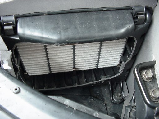
(note in this photo the bottom lip excludes water - a solid pipe going to airbox means every bit of water, grit and bugs end up in the filter - not so with the BFI)
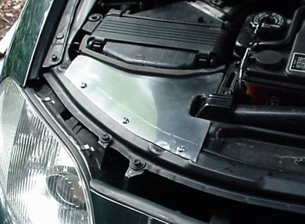
- front vertical face cut out completely leaving a 5 mm vertical rim around the hole (15mm across the top! - need this much space for sealing later on - in the above photo the top rim is too small!).
Note in this photo how high the foam has to be to seal against the bonnet. The gap above the airbox is quite large (3.5 cm)
EVA closed cell foam to seal edges of box to car surfaces above, below and to sides. (3.5 cm gap above airbox lid to bonnet when closed! - I though it would be much closer).
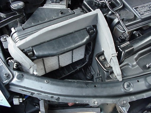
2. Under the headlight
(note how thick the foam has to be to seal against the headlight - with the headlight in place you can feel under it with your hand to make sure it seals. Don't put too much in their - you want the headlight to fit nicely - no bulge up. See how I had to have two goes at it buy sticking another layer of foam on top of the first estimate!)
Why stick a pipe under here to introduce more friction losses and make fitting a pain? - just use the bottom of the headlight as the roof and insert a piece of plywood below. Cut strip of EVA foam to smoothly direct air around. The strip has to be quite high to reach headlight. This gives maximum volume under headlight and minimises losses.
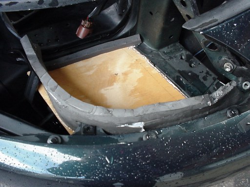
(on my active the plate rested on top of the suspension oil cooler - I had to bend the left hand support bracket out of the way to get the plate in. I always make a template out of cardboard first.)
You can see the flat bottom of the headlight here (above right) - it is used as part of the air intake
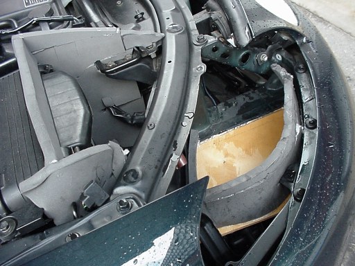
3. Chamber between the high beams.
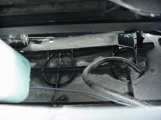
(This is a confusing photo at first - this is looking down in front of the radiator - you are looking at the top of the plastic shroud that diverts air to the radiator. The edge nearest the front has been lowered and now scoops air. The sensor is on the right))
No use fitting a pipe into here through the triangular hole - just makes it smaller and flows less and delivers sand and bugs and water to filter. The chamber separates water, bugs and dirt from the airstream if left alone. It is nice and big - holds a big store of pressurised air ready for stomping on the throttle. All you need to do is lower the leading edge - the easiest and quickest part of the whole operation. The metal strip bars are removed and refitted once the leading edge is down. I had to relocate a denso sensor on the air filter side to above the leading edge instead of below it -easy. I supported the edge downwards with a column of foam strips in the middle. The left hand leading edge is now down to the centre horizontal bar (half way).
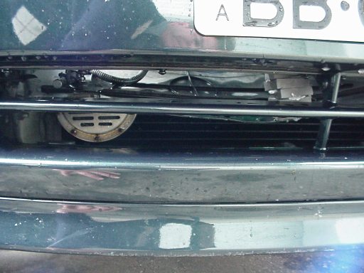
(close up of the intake below licence plate - see that stack of foam holding the edge down? - it looks terrible! - did the job but it is getting replaced - that's me grunting to get down low for photo in bumper reflection.)
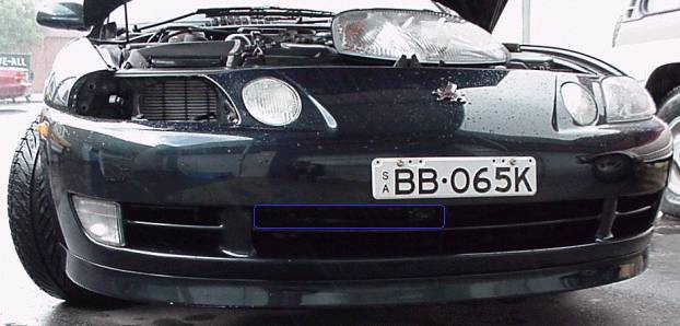
(The air intake is the blue rectangle - the black backing plate for the licence plate is removed and a skinny plate installed so no air flow is affected)
The right hand side gradually returns to original postion.
Used hot glue gun to attach foam everywhere - easy and quick. (no don't! - use the bolts listed in BFI Hardware instead)
That's it.
Could tune it for maximum boost by juggling leading edge and sealing headlight opening near battery but she'll be right for now. Time for a rest.......
The foam is more like a rubber mat you buy from a camping store. It is 12 mm thick, you roll it up and stick it on your backpack when hiking. It is called EVA closed cell (no air or water can pass through) foam. Looks like a light weight rubber. I cut it out with scissors and used it to fill in the gaps everywhere. The bonnet crushes it when closed to make a perfect seal. No expanding foam squirted anywhere here.
Air gets to filter by coming in under the licence plate, up between the two highbeam lights, then under the headlight and in. I'll get some pics soon to make it clearer.
The plastic curved piece that goes from the front top of the radiator down to the two long air intake slits below the licence plate is now the scoop for the incoming air.
I lowered the leading edge of it and it now scoops in air to go above it. The amount of air available for the radiator is now reduced.
I have a skinny licence plate that does not protude below into this air intake area. The black plastic licence plate holder has been removed and stored in a special spot (well it is a spacer for the rear licence plate at the moment).
Barry I don't know about a kit - the first step will be a DIY instruction page. We might be able to mass produce a few little bits that bolt in easy (like the under headlight part - that could save time), the front scoop and chamber is a real easy DIY, the airbox mods take a bit more time - cutting the hole is a bit fiddly ( I broke one blade and bent the other, I was rushing a bit I suppose, then filing the hole put plastic bits everywhere, left the filter in to protect the AFM, had to clean the filter of plastic bits afterwards - no problem on a TT) - getting the foam to the right size took a bit a customising - we could probably precut some foam to save everone having to mesure and cut there own. I'll put some pics up and people can have a look and suggest improvements etc.
I know the word descriptions are a bit tedious and foggy - so once we get the pics up people can start thinking of ways to make it better.
We can't get a new intake box in Australia unless we specially import one. Wreckers sell them for up to $200.
Has anyone heard of better prices from wreckers?
Fitting a nice neat cover over the whole lot might be another option. My airbox mod is not reversible (since there are bits everywhere and I did it in two stages). If you were really patient you could get it plastic welded back in.
I reckon fitting a nice neat polished alloy cover over the whole lot from the front of the air box to the rad support bar would spruce it up enough to satisfy the next buyer. Or maybe in black to suit the rest of the engine bay. Or maybe in Blue and we can put a TRUST sticker on on it!
Naturally if we did put a kit together then we would have to advertise it and put some facts together:
"The BFI air filter system is by far the best performing and best looking automotive air filter money can buy..."
"The ultimate in both air filtration and air flow for maximum engine performance..."
"Accept No Imitations..."
"...Doubles the air flow...adds up to 15 extra horsepower..."
Wow! - It does sound better now!
(hmmmm - they sound familiar don't they? - all of the above quotes are from Pod containers and websites)
Notice the quality and attention to detail (haha);
13 kW (17 HP) extra power with this cold air intake on a V8 over the standard airbox.
Sounds a lot to me. The G-tech pro takes weight or car in pounds, terminal speed at end of quarter mile and estimates rear wheel horsepower from a reliable formula.
This formula is available as a push button website here:
Measure your own 400m and terminal speed, weigh your car with driver and click on the buttons - out pops estimated rear wheel horsepower.
More accurate than a dyno for measuring extra horses that are dependent on air flow (like a cold air intake). A dyno fan doesn't do 100 km/hr winds. The fancy AP/AC-22 range of performance meters also take into account drag coeff and frontal area to estimate rear wheel horsepower.
See all three performance meters here:
Anyway that 13 kW figure I came up with was the "measure your own distance and terminal speed then click on the buttons at the website" method. The errors involved with the terminal speed and distance measurement make me shudder and wouldn't stand up in court but there you go. That's what I got consistently.
I have noticed then when I talk to people about improvements in the intake system of say 9cm of water (by fitting the $8 BFI), their eyes glaze over, they look over my shoulder and say things like "oh really, that's good Pete...". hmmmmmmmm - are they really listening to me? - or just humouring me?
But when there is talk of kW or HP improvements suddenly everyone's got banana's in their pockets!
So I am slowly painfully going to try to estimate hp increases as well.
Barry - all those quotes weren't mine - they were Blitz, K&N, Apexi, HKS etc - I can't take the credit for those beauties!
Anyway I want to have another look at the horsepower increase thing - if I can replicate it on a another car with a G-tech I'll be happier.
(I'll also try it on my car again). So any volunteers with a V8 and a G-tech (or a stopwatch) who want to try a BFI (I'll help put it on - or I'll stay away!) give me a hoy.
So here goes:
BFI - 17 HP gain !
I had some clear acrilyic plastic sheet (3mm) lying around so I made it into a clear cover that buts up to the front of the airbox (for the BFI). I plan to put a $14 blue neon light under it - especially good for showing off an aftermarket filter (lets face it - if you spent $180 on a fancy fitler might as well show everyone!). There is is certainly a market for a blue neon clear airbox mod don't you think? We could engrave it with BFI - kind of like those fancy installs of subs and amps in top line car stereo mags!
Anyway down at the hardware store up the back was a sheet of aluminium -so I have some of that to make a polished alloy cover too. The plastic one was a bit too thick at the front to seal easily under a closed bonnet - it needs to be trimmed back - no such problems with the aluminium sheet - it will fit under front rubber bonnet seal no problems.
Both methods are a lot neater looking than trying to seal airbox to underside of bonnet - There are even predrilled holes in radiator support bar ready to attach cover.
I'm also going to modify the front chamber today to seal battery side triangular hole and increase size of inlet (go all way across) - see if we can raise the pressure at 100 kph above 6cm of water.
It was interesting to note Aaron's V8 dyno run that a reduction of 2.5 inches of water gave a 4 kW increase (removing the standard filter). If we interpolate this forwards and backwards (I bit rough I know but interesting ), then we get a 2 kW gain from a K&N filter (2kW has been reported in other tests in magazines) and a 14 kW gain from the BFI (I roughly calculated 13 kW from terminal speed measurements).
hmmmmm....
The headlight area is critical because all of the cold air that enters the airbox must come through the space under the headlight. This space should be kept as large as possible. Putting pipes under the headlight reduces the area and introduces friction losses (less flow). No matter what I did I got the highest flow rate with nothing under the headlight.
(good thing about hot melt glue is that it peels off. Notice the foam strip that was glued across the airbox lid has been peeled off leaving no marks - it's great stuff. I recommend getting one, I got the smaller one for $22 on special - get some hot melt glue sticks while you are there - the two sticks that come with it don't last long. I also found that if you use it when it first gets runny, or not too hot, it peels off better. If you let the glue get real hot it sticks a lot better.)
Still needs work - I think it would look better if I sealed it against the airbox without that big grey piece of foam strip across the front - make it hidden by putting it under the cover. It would also look better if made by someone who knew what they were doing!
Here is another hint for the DIY BFI craftsman - leave a lip of about 10-15 mm (1/2 inch) of the front vertical face of the airbox at the top - this gives enough room to seal a horizontal plate from the radiator support bar. I cut my hole to leave only a 5mm lip and I am struggling.
To duct high pressure to the airbox you need to put a plate and curved deflector under the headlight (see previous photo). Then you want to modify the plastic curved shroud in front of the radiator to become a massive airscoop (see previous photos).